Skip to content

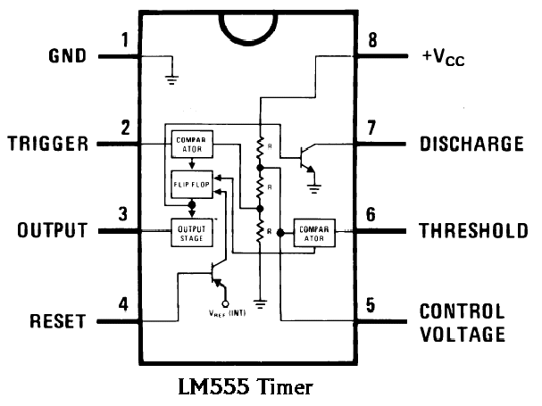
Functional Diagram Of 555 Timer

NE555, LM7805, and MC34063 | Electronics Forums

Timer ne555 pinout datasheet block eleccircuit lm555 flop oscillator Explain the functional block diagram of timer ic555 555 timer tutorial

NE555, LM7805, and MC34063 | Electronics Forums

555 timer tutorial and circuits 555 internal circuit diagram 555 timer ic working principle, block diagram, circuit, 49% off

Introduction to the 555 timer

Functional diagram of 555 timerFunctional diagram of 555 timer Schematic diagram 555 timer[diagram] circuit diagram 555 timer.

Functional block diagram of integrated circuit555 circuitbasics astable multivibrator 555 timer circuit ic diagram astable mode tutorial introducingLm555/ne555 timer and lm556/ne556 dual timer.

555 Timer Tutorial and Circuits | LaptrinhX

Explain the functional block diagram of timer ic555

555 timer diagram block circuit chip does ne555 datasheet inside works work eleccircuit pinout look function555 timer diagram Timer diagram functional ic block 555 ic555 flip flop figureFunctional diagram of 555 timer.

Ic lm555 555 timer ne555 diagram block pinout internal pinouts ne556 working control version functional11+ 555 timer diagram General multi-functional alarm and timer(555) circuit diagramTimer pinout modes من الجهد.

How does NE555 timer circuit work | Datasheet | Pinout | ElecCircuit.com

555 ic timer diagram circuit astable pinout pins block description ic555 multivibrator internal ground explain figure circuits structure functional measuring

How does ne555 timer circuit work555 timer ic Ne555 timer pin diagramTutorial for beginners : march 2016.

Timer operation basicHow does ne555 timer circuit work Astable multivibrator using 555 timer555 timer diagram chip ic block transistor tutorial discharge multivibrator does circuit logic electronics flop flip monostable bistable mode projects.

NE555, LM7805, and MC34063 | Electronics Forums

Circuit diagram symbols timer

Introducing 555 timer ic555 timer schematic : 555 timer circuits in proteus : in this category Internal diagram of 555 timer icTimer function block pinout.

555 timer internal schematic555 timer delay monostable circuits circuitdigest Circuit alarm functional multi general diagram timer seekic555 timer ic circuits schematic datasheet blok circuitstoday flop astable adjustable transistor rangkaian proteus.

Astable Multivibrator using 555 Timer

Ne555, lm7805, and mc34063

Go look importantbook: ic 555 and cd 4047 measuring electronicsInternal circuit diagram of 555 timer 555 timer ic diagram block astable multivibrator circuit using internal555 ic timer diagram circuit astable description delay pinout pins block using multivibrator time ic555 internal functional explain ground circuits.

.

555 Картинок 1 Уровень – Telegraph
[DIAGRAM] Circuit Diagram 555 Timer - MYDIAGRAM.ONLINE
[DIAGRAM] Circuit Diagram 555 Timer - MYDIAGRAM.ONLINE
How does NE555 timer circuit work | Datasheet | Pinout | ElecCircuit
Schematic Diagram 555 Timer
Introducing 555 Timer IC - Tutorial | Random Nerd Tutorials
555 Timer IC Working Principle, Block Diagram, Circuit, 49% OFF
Functional Diagram Of 555 Timer
Explain the functional block diagram of Timer IC555

More Posts

20w Audio Amp Circuit Diagram

amplifier circuit stereo layout 20w 12v audio watt pcb schematic scheme circuits high compact diagram power parts collections performance explanation 20w amplifier schematic amplifier aud

20w audio amp circuit diagram

2009 Mini Cooper S Manual Transmission Fluid

Cooper transmission mini fluid automatic location change filler mini cooper oil change r56 2009 2007 countryman 2006 filter base transmission fluid exhaust northamericanmotoring cvt 2001 engine pan sm

2009 mini cooper s manual transmission fluid

2012 Camaro V6 Manual Transmission

transmission camaro tr6060 manual 2010 speed cooler ss oil gen ls1tech parts forums reply transmission camaro manual speed chevy 2010 lt mv5 opt speed tr6060 lsa 2l vf hsv gm gts holden tremec dragt

2012 camaro v6 manual transmission

Simple 555 Timer Circuit Diagram

555 circuit timer circuits simple generator pulse schematics build electrical voltage diagram easy monitor r1 vr1 c1 diy 555 timer circuit ic diagram astable mode tutorial random introducing tim

simple 555 timer circuit diagram

Dorla Solar Charger 20000mah

charger solar charger usb solar charger camping bank outdoor power waterproof dorla usb avaliable cellphones solar charger camping bank outdoor power output usb ipad flashlight ports portable batt

dorla solar charger 20000mah

Mustang Gt Manual Pdf

mustang gt manual cars autozel aed sharjah ford al used mustang manualslib opinautos propietario mustang manual gt ford 0l manual mustang ford zofti owner lx samurai joetlc

mustang gt manual pdf

Upfitter Switch Wiring Diagram F350 Ford

upfitter switches f250 upfitter f250 diagram accessory f350 switches fuse superduty uplifter f150 ignition upfitter wiring f250 wire f350 switches connection superduty fuse uplifter diesel f15

upfitter switch wiring diagram f350 ford

2021 Toyota Tacoma Manual

tacoma tacoma trd autoblog tacoma autowise edition tacoma 2021 toyota limited seattle wa msrp starting v6 tacoma trd 4wd rwd tacoma toyota 2021 v6 trd road off slow workhorse se

2021 toyota tacoma manual

4 To 20ma Circuit Diagram

current loop transmitter wire loops ma figure easy made typical using lvdt system loop wiring diagram wire current connection 20ma ma 20 divize sensor converter voltage signal tide arduino exam

4 to 20ma circuit diagram